Stokes Flow in Porous Media
.I consider the steady-state Stokes equations in porous media with parabolic inflow boundary condition and natural outflow boundary condition. Numerical solution is obtained by using the MAC scheme which is a direct discretization using second order finite differences on a staggered grid. My code was written in MATLAB which is capable of generating numerical solutions with input image of any porous media.
Numerical solution of velocity profile in the porous media generated by MAC scheme
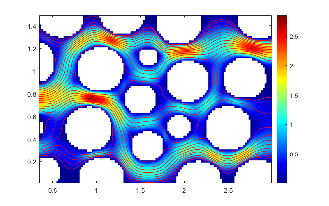
Example 1: 2-dimensional Stokes flow
in a randomly generated porous media |
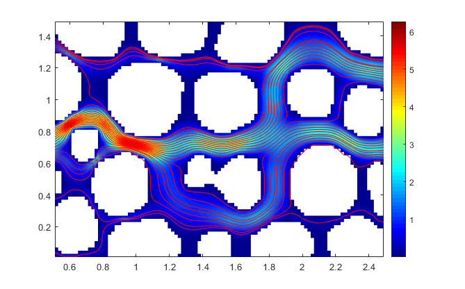
Example 2: 2-dimensional Stokes flow in a porous media
obtained from glass beads experiment |
|
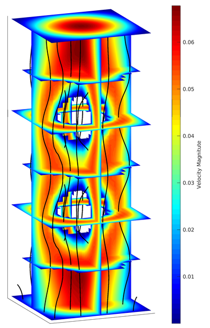
Example 3: 3-dimensional Stokes flow
in a porous media 
Consider a 3-dimensional from through a porous media (above figure) with paraboloidal inflow boundary condition at the bottom and no-slip boundary condition on the lateral walls. I used the natural boundary condition at the top (outflow). The figure on the right shows the velocity of fluid with streamlines in black.
|
|
Hydrate Formation in Sand with and without the Phase-Field Model
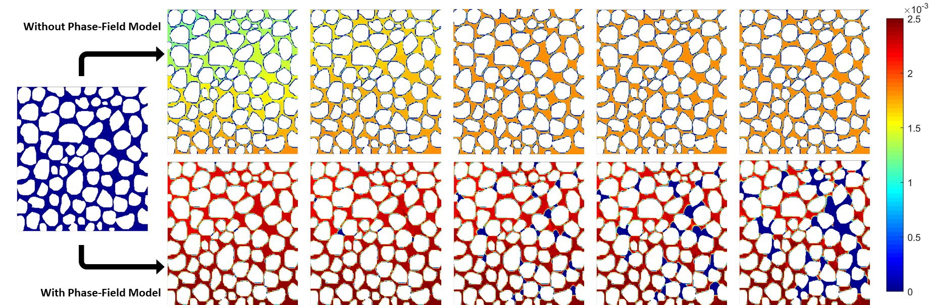
The methane gas transport in GHSZ is highly diffusive flow. Hence, if we simulate the advection-diffusion transport in the sand, it is unlikely to see any hydrate formation in pores. Above figures have rock in white and methane fraction in color (blue to red). Upper row of figures show the evolution of methane concentration over 100 kyrs. Since the methane concentration never reaches the maximum solubility, we don't see any hydrate formation. In reality, hydrate can present in the pores. To simulate hydrate formation in the pores, we run the simulation of methane gas transport using a coupled transport-phase-field model. The bottom 5 figures show the special case of the evolution of methane concentration over 100 kyrs. When the advective velocity takes over the diffusion rate at narrow necks of pores, the methane concentration can exceed the maximum solubility and hydrate forms (blue).
